Custom 4ch Mixer / 2ch Attenuverter

This was the second module I built, after building my SD card wavetable thing. I quickly realized you can't do a whole lot with a single mono channel, and I think I learned more about analog electronics from this circuit than any other one.
If I had it to do again, I would have built this as my first module. It's an easy first project, it comes together for a couple bucks in jellybean parts, and it's immediately useful in a bunch of different ways.
Design
For this board, I believe I referenced a combination of schematics. There are a few on musicfromouterspace.com, but sadly it's all iframe-based and you can't easily link directly to things. The "Oldies But Goodies" section is full of great, simple utility module schematics. Mono Audio Mixer #1 is probably the one I referenced.
The Op Amp
Ah yes. The Operational Amplifier. These are important, and get used just all over the place, and will take repeated viewings and gentle contemplation to start to understand in an intuitive way. I am still working on this. At its simplest: it wants to keep its two inputs exactly the same voltage, and will drive its output in whatever direction will do so.
This introduction by W2AEW (bless him and his fine works, I have learned a lot from his videos) lays a nice foundation. And if you're like me, you'll watch this and it will not be clear at all why you would want one of these devices. A lot of electronics introductions can land as somewhat impractical and academic. But in analog synths, there are all of these simple circuits that are incredibly handy to have in your case, incredibly cheap to build, and let you apply some practicality to otherwise heady theoretical stuff.
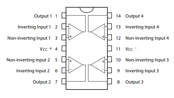
ANYWAYS: the op amp. It is a chamelion. A three-legged magical rune. A Swiss Army Knife for electricity where different configurations of cheap components can make it twist and bend an electrical signal in all sorts of fun ways. They are so handy that often they'll throw two or four of them in a single chip for convienience. Here's how they are laid out, in the TL074 that I used: one on each corner, all sharing a single power supply on the middle two pins.
The Mixer Stage
Two of the four op-amps in this chip are used to drive the mixer. In electronics, at least the kinds I work on, it is easier to buffer or amplify a weak signal while also inverting it, than it is to amplify it without inversion in one fell swoop. So, since we have all these op amps lying around everywhere, it's usually easier to just invert it twice.
Our mixer takes in 4 mono sound signals. Each is first AC decoupled through a capacitor, then sent through a 100k potentiometer for attenuation, and then through a 20k resistor into the negative input of the op amp.
Because the op amp wants to keep everything the same voltage, if we tie the positive input to the ground (0v), the output will try to put out an exact opposite copy of whatever it is seeing on the input. So we feed the output into the input with a 39k resistor.
And voila! This can be extended for any number of channels really. You feed very weak, mixed signals into the input, and you get a very sturdy strong copy on the output, albeit inverted phase.
Finally, we feed the output of that stage into another op amp on the chip configured in a similar way. Now we have a stronger signal to work with, so we add a knob to allow us to adjust the gain and actively amplify this signal more if we want. All that for a $0.50 op amp chip and a few pennies worth of passive components. And we still have two op amps we haven't used yet!
The Attenuverter
I really just wanted to toss something in here since I had some space left on my module, and two channels left on my op amp. I read about attenuverters somewhere, and they're basically what they sound like: a volume knob like normal, except that you can turn a signal down below zero and end up with an inverted version of that signal. I honestly mostly use this as a CV source for other stuff. It has gotten very rare use indeed as a signal inverter.
The Face Plate
After building the SD card module, I realized that drilling holes with a drill is for the birds. I have a 3D printer after all, I should be able to just have all these holes be pre-placed and perfect every time. I have a rickety old printer, so it took a couple calibration tests to get the hole sizes just right for the knobs and jacks I had, but then I just started building a big old blender file of face plates.
There is some spelunking to be done on old hard drives to track these files down, but I did put several designs over on Thingiverse.
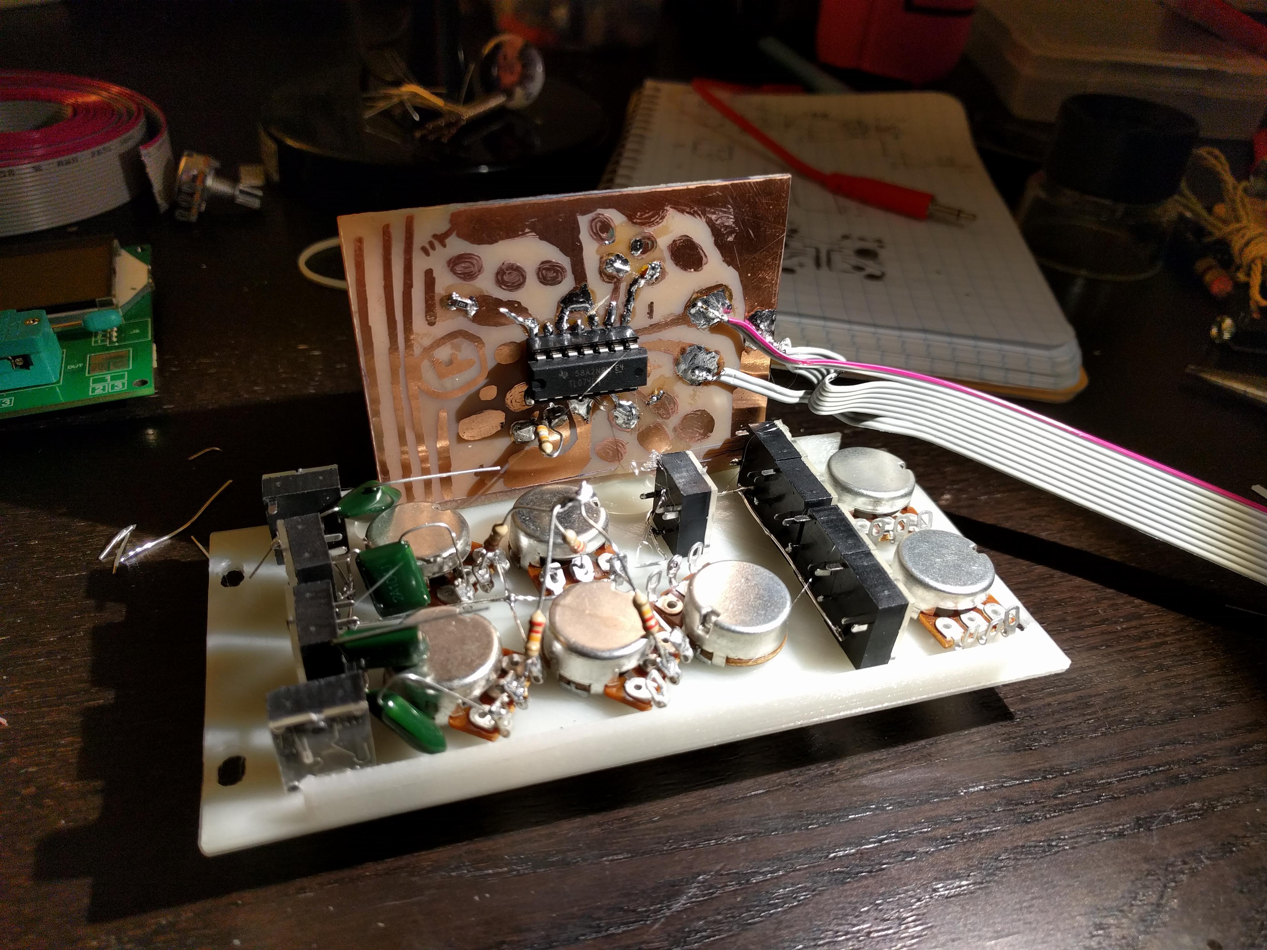
Construction
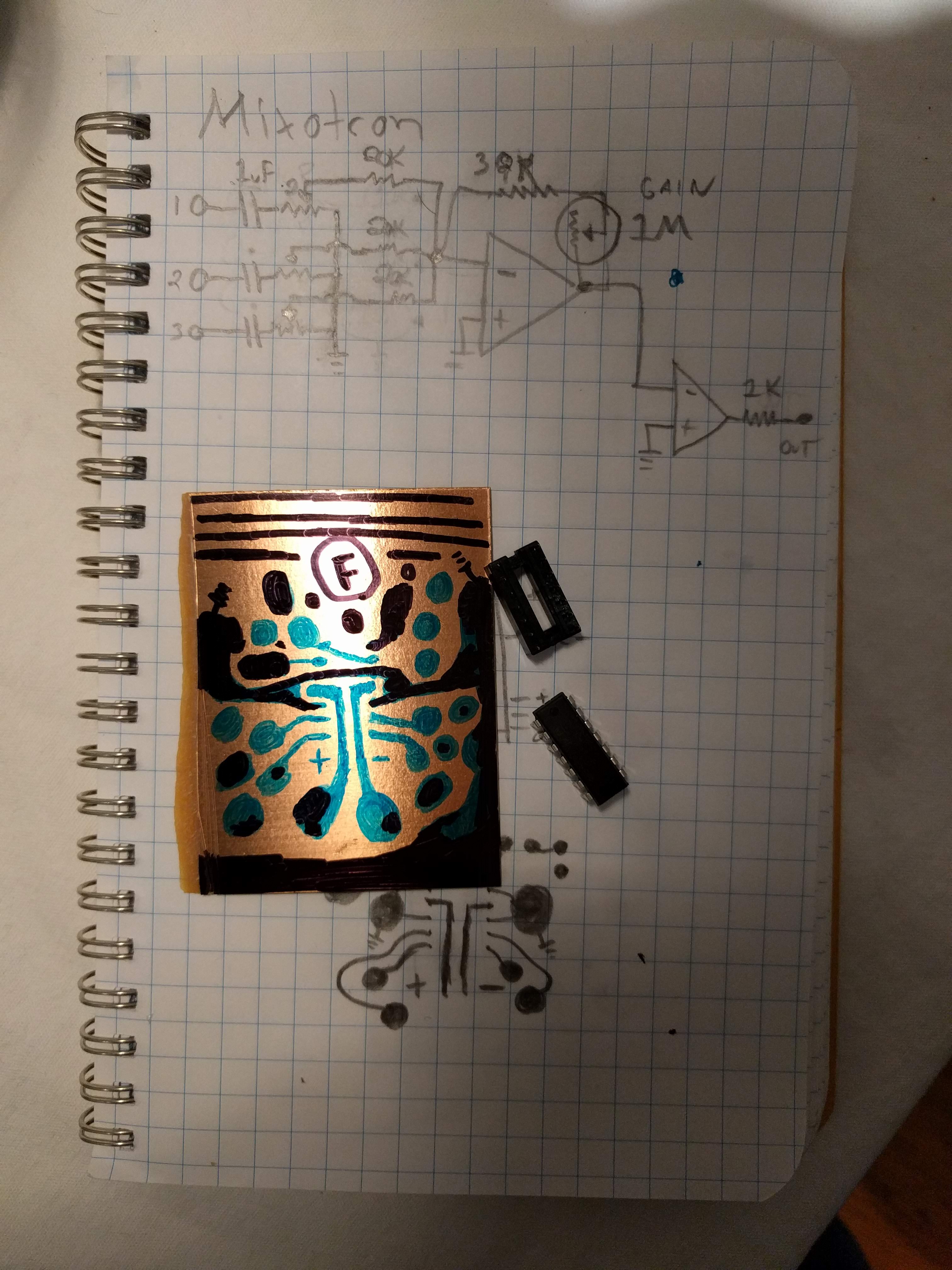
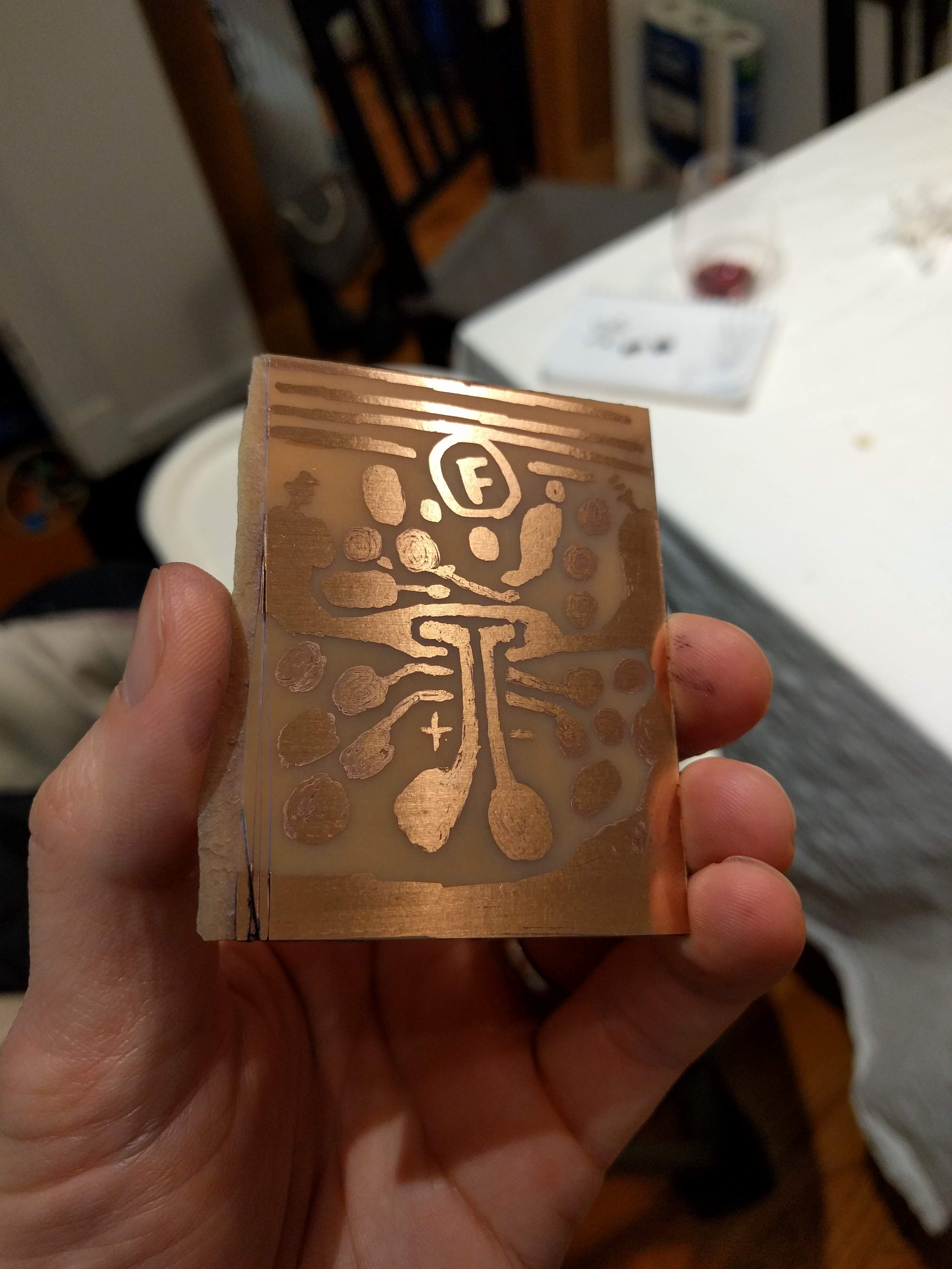
Since most of my passive components were going to get mounted right on my potentiometers and jacks, I laid the board itself out on copper-clad board by hand with a sharpie. You can design a proper schematic and PCB layout, and then print it out on a laser printer and iron it on and wash it off and yada yada. Or, if you just need one of something, you can just draw the traces and pads you need on some copper board with a sharpie, then swish it around in some ferric chloride, and then all the non-sharpied parts wash away and you are left with a hand-drawn circuit board of your very own.
I did not build that many modules this way ultimately, just my power supply and this, but it's a great, relaxing way to do circuit design. Using your hands and brain in repetitive ways on complex concepts helps you understand them.
I also designed and 3D printed all the knobs, which is another great use of even a very small 3D printer. You can grab these designs on Thingiverse too.